If you have spent any time working with Rockwell’s PlantPAx library, you are probably familiar with the P_DOut block. It is a solid, standardized way to control a discrete output, and it plays nicely with faceplates and alarm management out of the box. That said, there is one quirk that tends to create a bit of friction in ladder logic: the way it handles its command inputs.
P_DOut separates its on and off commands into two distinct signals, PCmd_On and PCmd_Off. Rather than accepting a simple latched bit that you hold high to keep a device running, it expects pulsed, one-shot style inputs. This design makes sense from a safety and handshaking standpoint, but in practice it means you cannot just wire a maintained control signal straight to the block. You need to manage the transition logic yourself.
For a single instance, that is manageable. You add a couple one-shots and move on. But once you have a project with a dozen or more P_DOut blocks, that same pattern gets copy-pasted all over your routine. It clutters up the logic, makes troubleshooting slower, and introduces more opportunity for inconsistency.
That is the problem this AOI was built to solve.
What the P_LatchToPulse AOI Does
The P_LatchToPulse AOI acts as a translation layer between a simple maintained signal and the pulsed inputs that P_DOut expects. You feed it a single latched control bit, and it handles the edge detection and pulse generation internally. On the output side, it hands you exactly what P_DOut is looking for: a one-shot pulse on PCmd_On when your control signal transitions high, and a one-shot pulse on PCmd_Off when it transitions low.
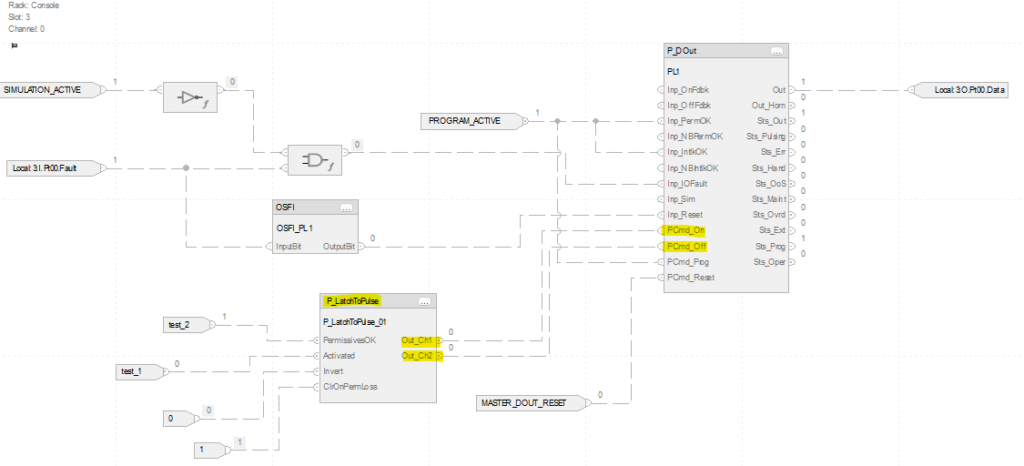
The result is that your control logic stays clean and straightforward. You drive a single bit based on your process conditions, interlocks, or operator commands, and the AOI takes care of the translation. No scattered one-shots, no additional rungs per device.
P_LatchToPulse AOI Features
The P_LatchToPulse AOI includes a small set of parameters designed to keep it flexible without overcomplicating it. Here is what is included:
- Invert: Flips the output channel assignment. By default, Channel 1 drives PCmd_On and Channel 2 drives PCmd_Off. With the Invert bit set, that behavior is reversed. This is useful when your wiring or device logic requires the opposite convention without reworking your control signal.
- PermissivesOK: Lets you feed a consolidated permissive bit into the AOI. Rather than scattering interlock logic throughout your routine, you can roll your permissive conditions into a single bit and pass it here. The AOI will only allow the LatchToPulse operation to run when this bit is high.
- ClrOnPermLoss: Gives you control over what happens when PermissivesOK drops out. When this bit is set, the AOI will automatically revert the output to its default state on permissive loss. If Invert is off, that means pulsing PCmd_Off. If Invert is on, that means pulsing PCmd_On. This is handy for applications where a loss of permissives should actively drive the device to a known state rather than simply stopping further commands.
Why an AOI Instead of Inline Logic
You could argue that the one-shot logic is simple enough to write inline each time. That is true. But there is real value in encapsulating it.
First, it is scalable. Drop the AOI into any program and it behaves the same way every time. There is no risk of someone wiring it slightly differently on the next project or forgetting a step.
Second, it is readable. When another engineer opens your routine and sees a P_LatchToPulse AOI connected to a P_DOut block, the intent is immediately clear. There is no need to trace through rungs trying to figure out why there are one-shots sitting between the control logic and the output block.
Third, it is maintainable. If the underlying behavior ever needs to change, you update it in one place. Every instance in the project picks up the change automatically.